
From a cursory read of the datasheet, using the “dead time control” pin seems to be the way to go. Basically, this pin is used to set the voltage, while the error amplifier inputs (that’s the closest function to “over current protection” this chip has) are used to adjust the output according to the load. For your application, you probably don’t need to use them at all.
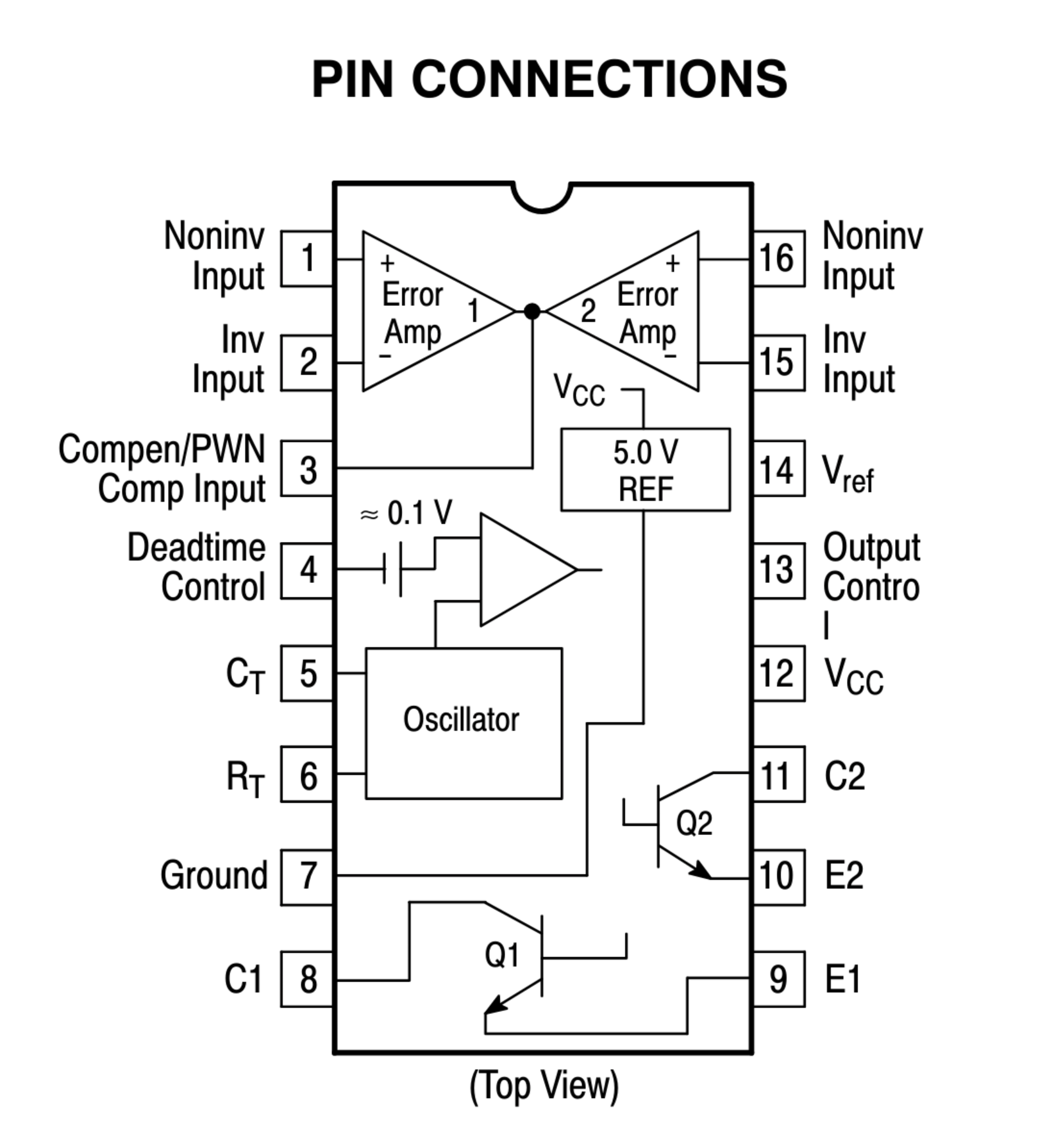
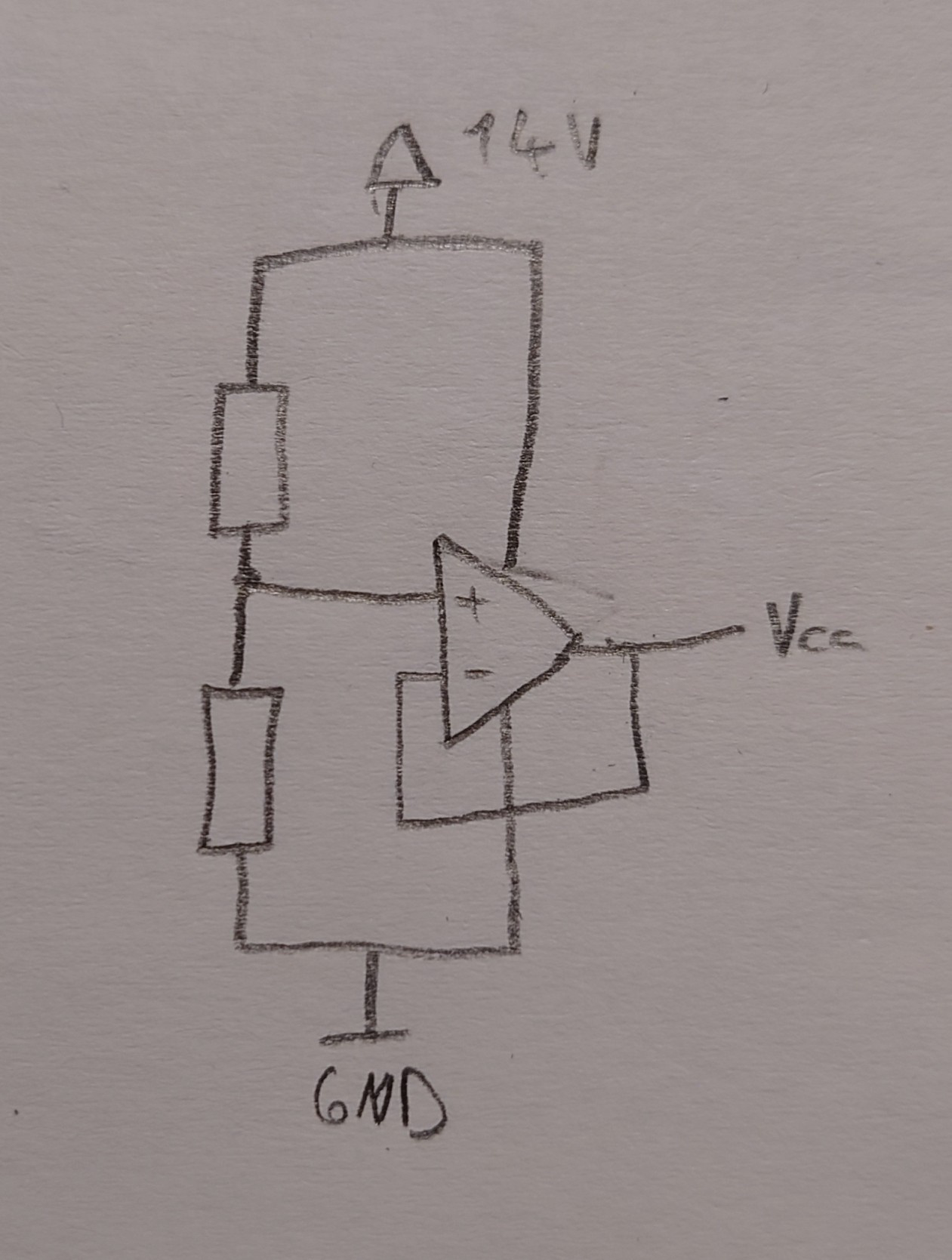
My instinct would be to disable the error amplifiers by connecting pins 1,2,15 and 16 to GND. You can then connect the wiper pin of the potentiometer to the deadtime control input, with the other pins of the potentiometer connected to GND and 3.3 V.
I haven’t worked with this chip before, so take this with a grain of salt. You should probably use a simulation tool to check the circuit before you start destroying chips.


You can use a boost converter to boost the 5V of an USB port to the 19V your notebook needs.
Assuming 5A output from a powerbank (which is probably about the max you will get without USB PD), you could theoretically get 0.55A at 19V. With the unavoidable inefficiencies, you will get less.
So, maybe enough to very slowly charge your notebook while it’s off. But when it’s turned on, the battery charge will still drop.